

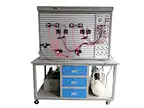
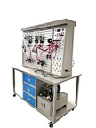

Basic pneumatic and hydraulic training device
GTPHT-0002
Delivery:
EXW
minimum order:
1 set
Supply Ability:
30set / Month
Country of Origin:
Guangzhou,China
Stock Time:
45Day
Technical parameter
Dimension: About 1500mm × 800mm × 1750mm
Power supply: input AC220V, 50Hz, output DC24V, AC220V
Weight: about 300kg
Dimension: About 1500mm × 800mm × 1750mm
Power supply: input AC220V, 50Hz, output DC24V, AC220V
Weight: about 300kg
Quantity:
The experimental device hydraulic and pneumatic trainer uses double-sided structure, is an experimental table hydraulic and pneumatic training device provides places for doing pneumatic and hydraulic test experiment for two groups of four students.The vocational training equipment hydraulic and pneumatic training device can simultaneously do double-sided comprehensive pneumatic and hydraulic experiments, optimizing and sharing resources and improving products’ performance. The overall structure of the vocational training equipment hydraulic and pneumatic training device is simple and practical. The hydraulic and pneumatic trainer vocational training equipment uses transparent hydraulic components for easy understanding of the work principle of the hydraulic system.The hydraulic and pneumatic trainer is also suitable for the teaching and skills training in higher vocational colleges and secondary vocational colleges.
Technical parameter
Dimension: About 1500mm × 800mm × 1750mm
Power supply: input AC220V, 50Hz, output DC24V, AC220V
Weight: about 300kg
Product description
The experimental device uses double-sided structure, is an experimental table provides places for doing pneumatic and hydraulic test experiment for two groups of four students. It can simultaneously do double-sided comprehensive pneumatic and hydraulic experiments, optimizing and sharing resources and improving products’ performance. Its overall structure is simple and practical. It uses transparent hydraulic components for easy understanding of the work principle of the hydraulic system.
Product composition
Pneumatic:
No. | Name | Specs | QTY |
1 | Experimental bench | 1 pcs | |
2 | Components installation panel | Relay control unit, Signal input unit, | 1 pcs |
3 | Air compressor | 10L, 0.7Mpa | 1 pcs |
4 | Single-acting cylinder | MSAX25×100-CA | 1 pcs |
5 | Dual-acting cylinder | MAX25×100-CA | 2 pcs |
6 | Oil-water separator | AC2000 Triple pieces | 1 pcs |
7 | Reducing valve (with pressure gauge) | AR2000 | 1 pcs |
8 | 5/2 Handle shuttle valve | 4H210-08 | 1 pcs |
9 | 5/2 Single solenoid shuttle valve | 4V210-08(DC24V) | 2 pcs |
10 | 5/2 Double solenoid shuttle valve | 4V220-08(DC24V) | 1 pcs |
11 | 5/3 Double solenoid shuttle valve | 4V230-08(DC24V) | 1 pcs |
12 | 5/2 Single pneumatic control | 4A210-08 | 2 pcs |
13 | 5/2 Double pneumatic control | 4A220-08 | 2 pcs |
14 | 2/2 knob valve | MOV-02 | 1 pcs |
15 | 2/2 button valve | MOV-03A | 1 pcs |
16 | “OR” gate shuttle valve | ST-08 | 2 pcs |
17 | Quick exhaust valve | QV-08 | 2 pcs |
18 | One-way throttle valve | KLA-08 | 2 pcs |
19 | One-way throttle valve (install on the cylinder) | JSC601 | 7 pcs |
20 | One-way valve | 1/4 | 2 pcs |
21 | Sequence valve | Designed and made | 2 pcs |
22 | Air capacitor | Designed and made | 1 pcs |
23 | Six-way valve | Designed and made | 2 pcs |
24 | Magnetic switch | Designed and made | 4 pcs |
25 | Tools | 1 set | |
26 | Accessories | 1 set |
Hydraulic:
No. | Name | Specs | QTY |
1 | Experimental bench | 1 pcs | |
2 | Components installation panel | Relay control unit, Signal input unit, | |
3 | Drag motor and speed controller | 400W, 1500rpm | 1 set |
4 | Gear oil pump | 10L/min, 0-1.6Mpa | 1 pcs |
5 | Hydaulic oil tank | 1 pcs | |
6 | Auxiliary hydraulic oil tank | 1 pcs | |
7 | Cylinder stopper plate | 2 pcs | |
8 | Cylinder (with stroke collision block) | 2 pcs | |
9 | Spring return cylinder | 1 pcs | |
10 | Pressurized cylinder | 1 pcs | |
11 | Check Valves | 2 pcs | |
12 | Pilot Operated Check Valves | 2 pcs | |
13 | Overflow valve | 2 pcs | |
14 | Throttle valve | 1 pcs | |
15 | Speed control valve | 2 pcs | |
16 | Sequence valve | 2 pcs | |
17 | Pressure reducing valve | 1 pcs | |
18 | 2/2 solenoid valve | 1 pcs | |
19 | 4/2 solenoid valve | 2 pcs | |
20 | 4/3 solenoid valve | O type | 1 pcs |
21 | 4/3 solenoid valve | H type | 1 pcs |
22 | 4/3 solenoid valve | M type | 1 pcs |
23 | 5/3 solenoid valve | 1 pcs | |
24 | Pressure relay | 1 pcs | |
25 | Limit switch (normally closed) | LX19-001 | 2 pcs |
26 | Limit switch (normally open) | LX19-001 | 2 pcs |
27 | Pressure gauge | 0-1.0Mpa | 3 pcs |
28 | Three way | 2 pcs | |
29 | Four way | 2 pcs | |
30 | Tools | 1 set | |
31 | Accessories | 1 set |
Training course
Pneumatic:
1. The reversing loop of single acting cylinder
2. The reversing loop of double acting cylinder
3. Single acting cylinder speed control loop
4. Single phase speed control loop of double acting cylinder
5. Double acting cylinder speed control loop
6. Speed switching loop
7. Buffer loop
8. Secondary pressure control loop
9. Counting loop
10. Delay loop
11. Interlocking loop
12. Single cylinder and single reciprocating control loop
13. Single cylinder continuous reciprocating action loop
14. Sequential action loop of a straight cylinder and a rotating cylinder
15. Multi cylinder sequential working loop
16. Double cylinder synchronous action loop
17. Four cylinder linkage loop
18. Unloading loop
19. The application loop of the “OR” gate shuttle valve
20. The application loop of the fast exhaust valve
21. High and low voltage switch over control loop
22. Overloading protection loop
Hydraulic:
1. The reversing loop by using reversing valve
2. The locking loop by using “O” functional reversing valve
3. The locking loop by using hydraulic controlled one-way valve
4. Pressure setting loop
5. Two stage pressure loop
6. Reducing loop by using reducing valve
7. Boost loop by using pressure cylinder
8. Unloading loop by using reversing valve
9. The oil inlet throttling speed regulating loop
10. The oil return throttling speed regulating loop
11. The variable pump speed regulating loop
12. Compound speed regulating loop with gear pump and speed regulating valve
13. Speed transition circuit with short connected flow valve
14. Two times feed loop in series of speed regulating valve
15. Two times loop parallel to the speed regulating valve
16. Sequent circuit by using sequence valve
17. Sequent circuit by using pressure relay
18. Sequent circuit by using electrical stroke switch
19. Sequent circuit by using motion valve
Recommend Products
 Electro-Pneumatic Training Sytem Pneumatic trainer kit Educational Equipment Vocational Training EquipmentGTPT-0004Send Inquiry
 Educational Equipment Basic Electro Hydraulic Trainer with manual and electrical control KitGTHT-0004Send Inquiry
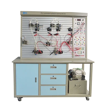 PLC controlled hydraulic training deviceTechnical parameter Dimension: 1500mm × 650mm × 1750mm Power supply: Single phase AC220V, 50Hz Weight: about 200kgGTHT-0001Send Inquiry
 PLC controlled pneumatic and hydraulic training device industrial training equipmentTechnical parameter Dimension: 1500×800×1750mm Power supply: Single phase AC220V, 50Hz Weight: about 300kgGTPHT-0001Send Inquiry
Send Message