


Hydraulic training frames
GTHT-TC001
Delivery:
EXW
minimum order:
1 set
Supply Ability:
30set / Month
Country of Origin:
Guangzhou, China
Stock Time:
45Day
Quantity:
GT2026081303(R)
Technical parameter
Maximum working pressure: 2.5MPa Pump flow rate nominal: 6 liters/min.
Motor power: 0.35KW, 1,800 RPM, 110V
Oil tank capacity: 20L
Power supply: AC 110V, 60Hz
Worktable: 1410mm (L) x 700mm (W) x 1800mm (H)
Panel dimensions: 1200mm x 745mm x 20mm
Weight (kg): Approx. 150kg
Hydraulic oil type: 32# hydraulic oil
Product components:
1. Hydraulic training bench (industrial)
No. | Item name | Specifications | QTY | Image | |
1 | Training table | Four 2600 load-bearing universal casters are made of 1mm-2mm thick steel; the drawer has a beautiful and elegant appearance with a matte powder coating process. | 1 | 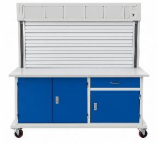 | |
2 | Training panel | 2.5mm Overlap with transition base plate | 1 | 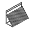 | |
3 | Pressure distributor | outlet | 130×100×25 aluminum profile | 1 |  |
4 | Pressure return oil distributor | 130×100×25 aluminum profile | 1 | 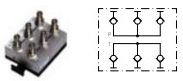 | |
5 | Component storage cabinet | 880×650×600 mm, steel, matte powder coated | 1 | 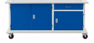 | |
2.Hydraulic pump station (industrial)
No. | Item name | Specifications | QTY | Image |
6 | Drive motor | Horizontal Vp-12 model with a milled iron casing and operating noise below 50 decibels | 1 | 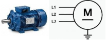 |
7 | Variable vane pump | Nominal displacement 6.67 mL/r | 1 | 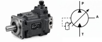 |
8 | Oil tank | 50 L, constructed with folded metal steel plate, thickened edging material for support, powder-coated surface, aesthetically pleasing | 1 | 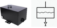 |
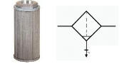
9 | Air filter | Modular mesh diameter φ32, flow rate greater than 20 L/min | 1 | 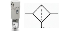 |
10 | Oil filter | MF-03 filtration accuracy 200 mesh | 1 |
|
11 | Oil temperature and level gauge | Iron-plated casing | 1 | 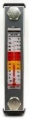 |
12 | Suction pipe | 300mm | 1 |  |
3.Hydraulic actuators (industrial)
No. | Item name | Specifications | QTY | Image |
13 | Double-acting hydraulic cylinder | 200mm stroke, rod diameter to piston ratio 1:2, | 2 | 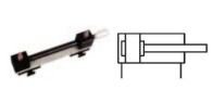 |
4.Hydraulic training bench components (industrial)
No. | Item name | Specifications | QTY | |
14 | Throttling valve, shut-off valve | CT-03 One-way throttle valve, threaded diameter M16, flow rate 24L/min, maximum pressure 35MPa | 2 | 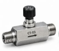 |
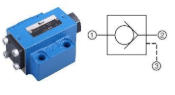
15 | Check valve | SA10, flow rate: 30L/min, maximum pressure 31.5 MPa, threaded diameter M16 | 2 | 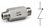 |
16 | Hydraulic check valve | SV10, diameter: φ10, maximum flow rate: 80L/min, minimum starting pressure: 0.5MP a | 2 |
|
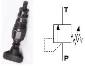
17 | Direct-acting relief valve | DBDH6, nominal diameter 6MM, maximum pressure 21.5MPa | 1 |
|
18 | Pilot-operated relief valve | DB10, nominal diameter 6MM, maximum pressure 31.5MPa | 1 | 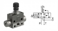 |
19 | Sequence valve | DZ10: Maximum flow rate: 150L/min, Maximum pressure: 31.5MPa, Pressure adjustment range: 0.3-21 MPa, equipped with aluminum mounting base. | 1 | 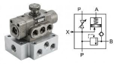 |
20 | Speed control valve | 2FRM5: Control flow 0.05-4L/min, Free flow control 20L/min, Max pressure 21 MPa, Equipped with two-port flow path plate, M16 thread. | 1 | 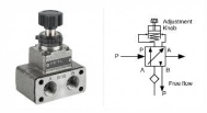 |
21 | Pressure reducing valve | DR10: Port diameter: φ6, Maximum flow rate 60L/min, Pressure adjustment range: 0.3-25 MPa, Maximum pressure 31.5MPa, Equipped with aluminum mounting base. | 1 | 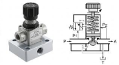 |
22 | 2-position 4-way solenoid directional valve (single) | 4WE6C-24: Two-position four-way valve, Flow rate: 60L/min, with transition oil passage plate, Port diameter φ6, DC 24V coil, with wire connector, with LED display. | 2 | 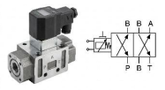 |
23 | 2-position 3-way solenoid directional valve (single) | 3WE6A: Two-position three-way valve, Flow rate: 60L/min, with transition oil passage plate, Port diameter φ6, DC 24V coil, with wire connector, with LED display. | 1 | 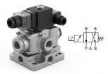 |
24 | 3-position 4-way solenoid directional valve (O) | 4WE6E: Three-position four-way valve. Flow rate: 60L/min, with transition oil circuit board, φ6 diameter, DC 24V coil, with wire connector, and LED display. | 1 | 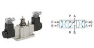 |
25 | 3-position 4-way solenoid directional valve (M) | 4WE6G: Three-position Four-way, Flow rate: 60L/min, with transition oil circuit board, φ6 diameter, DC 24V coil, with wire connector, and LED display. | 1 | 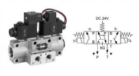 |
26 | 2-position 4-way manual directional valve | 4WMM: Two-position Four-way, Flow rate: 60L/min, with transition oil circuit board, φ8 diameter, DC 24V coil, with wire connector, and LED display. | 1 |  |
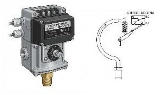
27 | Pressure relay | HHED40A15: Bourdon tube type. | 1 |
|
28 | 4-way | Made from aluminum profile, AL6063 aluminum ingot, with exquisite mold making. | 2 | 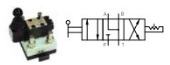 |
29 | 5-way | Made from aluminum profile, AL6063 aluminum ingot, with exquisite mold making. | 2 | 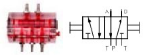 |
30 | Glycerin pressure gauge | 10MPa silicone oil vibration resistant. The inner red label shows the MPa and psi values respectively. | 3 |  |
5.Hydraulic training bench accessories (industrial)
No. | Item name | Specifications | QTY | Image |
31 | High-pressure hydraulic hose | Various sizes of oil pipes suitable for laboratory benches, metric threads at both ends, closedtype joints with built-in steel wire in the rubber layer, pressure resistance 28MPa, M16 quick connectors at both ends. | 1 |  |
32 | Quick-connect coupling (male) | 8mm diameter, with automatic closing function, leak-proof connection. | 1 | 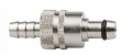 |
33 | Quick-connect coupling (female) | 8mm diameter, with automatic closing function, leak-proof connection | 1 |  |
34 | Hydraulic oil | Puli anti-wear hydraulic oil 32# | 40 | 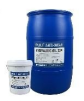 |
35 | Fixed bracket | Each bracket has a T-type locking knob | 4 |
|
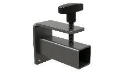
- Hydraulic training bench instruments (industrial)
No. | Item name | Specifications | QTY | Image |
36 | Speed sensor | Two-line | 1 | 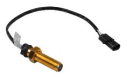 |
37 | Tachometer | ZN48 | 1 |
|
38 | Inductive proximity switch | PNP type, 24V, 0.5A, two-wire system, 1.2m wire length, high insulation class, oil-resistant corrosion-resistant | , 4 | 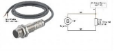 |
39 | Three-phase power meter | Displays motor three-phase power | 1 | 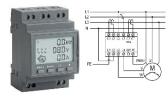 |

7. Electrical control unit for the hydraulic training bench (industrial)
No. | Item name | Specifications | QTY | Image |
40 | Programmable Logic Controller (PLC) | FX1s-20MR | 1 | 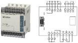 |
41 | Programming Cable | 1.5m | 1 |
|
42 | Switching Power Supply Module | WV output: DC24V 4.5A, AD12V 1.5A | 1 |  |
43 | Power Start/Stop Module | Includes three-phase four-wire leakage protection (output 110V) | 1 |  |
44 | Time Relay Module | HB48 includes 32 functions such as delay, cumulative time, frequency, and speed counting, and provides DC9V output | 1 |  |
45 | AC Contactor | 1 |  | |
46 | Button Module | Start button, stop button, programmable controller input/output, etc. | 1 |  |
47 | Hydraulic Simulation Software | English version | 1 |
8.Wear parts of the hydraulic training bench (industrial)
No. | Item name | Specifications | QTY | Image |
48 | Sealing tape | PTFE tape | 1 |  |
49 | Sealing gaskets | Φ16 | 2 | 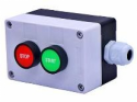 |
50 | Open/close connectors | Double interlocking connector | 1 | 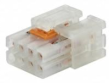 |
51 | Push-button switches | Mounting hole Φ10 | 1 |  |
52 | Fuses | 5A | 10 |  |
53 | Applicator plugs and sockets | Shanghai Jingyi | 1 | 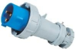 |
54 | Power cords | 5m | 1 |  |
55 | Three-phase four- wire plugs | 16A | 1 |  |
9.Common tools for hydraulic training bench (industrial)
No. | Item name | Specifications | QTY | Image |
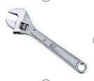
56 | Adjustable wrench | 6”
| 1 |
|
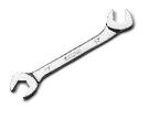
57 | Open-end wrench | 17-19 | 1 |
|
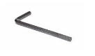
58 | Hex wrench | 1.5mm – 10mm | 1 |
|
59 |
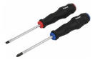
Screwdriver | Two types in total: single-line and cross-shaped. | 1 | |
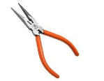
60 | Needle-nose pliers | Hugong | 1 |
|
This educational equipment is suitable for basic training in hydraulic control technology. Modular training set for teaching the fundamentals of hydraulics and hydraulic control technology, designed for basic-level practical exercises involving circuit assembly in a laboratory setting. Designed for educational purposes.
Didactic content:
- System for assembling hydraulic circuits on training bench.
- Detachable components and quick-connect fittings.
- Componentsdesigned for secure mountingand removal during repeated laboratory exercises.
- Hydraulic power unit featuring an electric motor, pump, reservoir, filter, safety/relief valve, pressure gauge, and necessary connections.
- Capability for pressure generation and control exercises.
- Capability for flow control exercises.
- Capability for directional control exercises.
- Capability for actuator operation.
- Capability for regulating advance and retract speeds.
- Capability for assembling differential circuits.
- Capability for comparing meter-in and meter-out flow regulation.
- Capability for analyzing force and speed in cylinders.
- Capability for using pilot-operated (unlockable) check valves.
- Single- and/or double-acting hydraulic cylinders.
- Manually operated directional control valves.
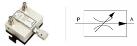
- -Flow control valves.
- Pressure Range: 0–120 bar
- Nominal Flow Rate: 1–10 LPM (compact training models)
- Process Connection: Leak-free quick-connect fittings or standard threads (G1/4").
- Adjustment: Manual adjustment via needle screw or graduated scale knob
- Body Material: Nickel-plated brass (pneumatic) or anodized steel/aluminum (hydraulic)
- Operating Temperature: -10°C to +60°C
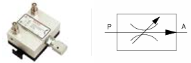
-Pressure control valves.
- Pressure Range: 0–120 bar
- Nominal Flow Rate: 1–10 LPM
- Process Connection: Industrial quick-connect fittings or G1/4"threads
- Adjustment: Manual via graduated scale knob or precision screw; includes knob lock on advanced models.
- Body Material: Nickel-plated brass (pneumatic) or anodized steel/aluminum (hydraulic).
- Integrated Accessories: Direct-reading pressure gauge (optional/standard on basic sets) and purge port.
- Operating Temperature: -10°C to +60°C.
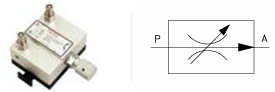
- Opening Pressure: 1 bar or 5 bar (interchangeable depending on the application).
- Maximum Working Pressure: 50 bar (hydraulic) / 10 bar (pneumatic).
- Nominal Flow Rate: Up to 5 LPM (modular training models).
- Pilot-Operated Function: Hydraulic release via external signal (direct or inverse logic).
- Process Connection: CETOP 3 modular plate or G1/4"threads.
- Body Material: Anodized aluminum or steel.
- Operating Temperature: -10°C to +60°C.
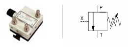
-Pilot-operated (unlockable) check valves.
- Maximum Working Pressure: 50 bar (pneumatic) / 120 bar (hydraulic).
- Nominal Flow Rate: Up to 5–10 LPM (depending on the modular size).
- Pilot Opening Pressure: Typically 30–50% of the maximum load pressure.
- Process Connection: CETOP 3 modular plate or G1/4"threads with leak-free quick-connect fittings.
- Configuration: Available in direct (pilot opens, reverse flow) and reverse logic; with internal or external drain depending on the application.
- Body Material: Anodized aluminum (pneumatic) or high-strength steel/aluminum (hydraulic).
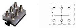
-Manifold/distributor.
- Maximum Working Pressure: 120 bar (typical in FH-401/FH-402 training sets).
- Recommended Operating Pressure: 60 bar.
- Nominal Flow Rate: Up to 10–15 LPM (depending on connection size).
- Process Connections:
- Inlets/Outlets via leak-free quick couplings.
- Typically 1 main inlet and 4–6 distribution outlets.
- Body Material: Machined steel or high-strength anodized aluminum.
- Integrated Accessories: Pressure monitoring gauge ports on each outlet line.
- Operating Temperature: -10°C to +60°C.
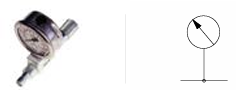
-Pressure gauges.
- Measurement Range: 0–100 bar (standard for educational systems up to 120 bar working pressure).
- Accuracy: Class 1.6% (high accuracy for calibration practice).
- Dial Diameter: 60 mm (clear reading at an educational distance).
- Process Connection: Standard G1/4"thread or leak-free hydraulic quick-connect.
- Distributor Variant: Integrated model with a 4–5 port manifold block for simultaneous monitoring of multiple pressure lines.
- Housing Material: Stainless steel or impact-resistant plastic.
- Operating Temperature: -10°C to +60°C.
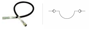
-Hydraulic hoses with quick-connect couplings.
- Maximum Working Pressure: 120 bar.
- Burst Pressure: Greater than 240 bar (typical safety factor >2x).
- Inner Diameter: Typically 4 mm or 6 mm (depending on the flow rate of the training set).
- Available Lengths: 600 mm, 1000 mm, 1500 mm (standard in sets FH-101/FH-102).
- Hose Material: Synthetic inner tube resistant to hydraulic oil, textile or metal reinforcement, abrasion-resistant outer cover.
- Connectors: Quick-connect couplings in steel or nickel-plated brass with manual release mechanism (push-pull or collar), compatible with standard training connections.
- Operating Temperature: -40°C to +125°C.
- Flexibility: Minimum bending radius of 80 mm to facilitate circuit assembly on panels.
Mounting accessories: complete hydraulic assembly, power unit, training bench or panel, cylinders, valves, hoses, connectors, pressure gauges
-Components clearly labeled or marked with symbols for educational use.
-Connections suitable for frequent assembly and disassembly without specialized tools or with minimal tooling.
-System suitable for safe operation in an academic laboratory.
Included scope: manuals in English, hydraulic diagrams, and practical exercise guide.
Practical exercise guide:
- Hydraulic Throttling Speed Control Experiments
- Meter-in throttling speed control circuit experiment
- Meter-out throttling speed control circuit
- Pressure Control Circuits
- Pressure regulation circuit with relief valve
- Two-stage pressure regulation with multiple relief valves
- Pressure regulating circuit of the hydraulic pump
- Pressure-Reducing Circuits
- Speed control circuit with pressure-reducing valve
- Two-stage feed circuit with pressure-reducing valve
- Unloading Circuits
- Unloading circuit with directional control valve
- Unloading circuit with relief valve and pressure relay
- Unloading circuit with pilot-operated relief valve
- Hydraulic Cylinder Synchronization Circuits
- Series synchronization circuit for hydraulic cylinders
- Reciprocating motion circuit for hydraulic cylinders
- Hydraulic Cylinder Sequential Action Circuits
- Sequential action controlled by proximity switch
- Sequence circuit controlled by time relay
- Cushioning Circuits
- Cushioning circuit with throttle valve
- Cushioning circuit with relief valve
- Directional Switching Circuits
- Directional switching circuit with solenoid directional valve
- Mid-position unloading circuit
Recommend Products
 Pneumatic training systemsGTPT-TC001Send Inquiry
 Station with four variable-control sectionsGTAM-TC001Send Inquiry
 VVTi actuator Experiment modelGTAT-VT2-15Send Inquiry
 Small transformer training modelGTAT-VT2-14Send Inquiry
Send Message